Utilities, campuses, and industrial plants cannot eliminate every transformer failure, but they can shape what happens next. The difference between a short-duration incident and a sustained pool fire often comes down to site layout, passive fire protection, oil containment, and the speed of electrical protection. This article explains how specific design and maintenance decisions influence fire behavior in real situations after a fault. It focuses on practical relationships among spacing, barriers, deluge, and condition monitoring, so facility and safety teams can plan for survivability rather than hope a failure never occurs.
What a Failure Looks Like at the Equipment Pad
When internal insulation breaks down, arcing inside the tank can vaporize mineral oil, spike pressure, and eject hot oil through a pressure relief device or tank seams. Ignition can occur at the arc, at a ruptured bushing, or where atomized oil meets a hot surface. Many facilities first ask why do transformers blow; understanding the initiating fault helps, but so does preparing the yard so a jet fire or spill does not escalate.
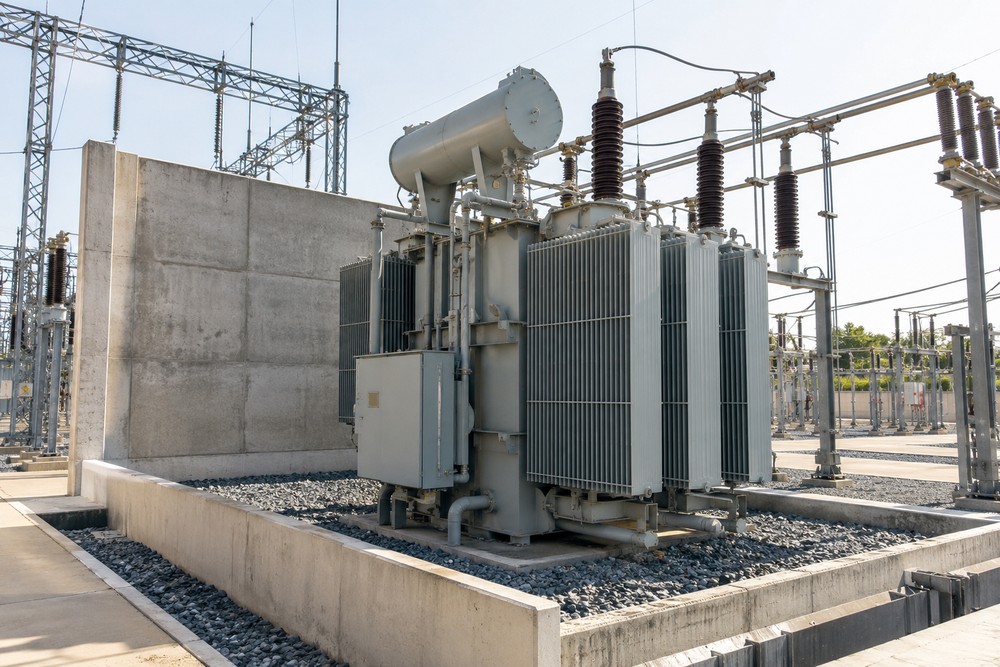
Once burning oil is outside the tank, radiant heat and flame impingement threaten adjacent transformers, cable trays, and control houses. Direct exposure matters: a clear path from the flame plume to another oil-containing unit or a wall opening can raise temperatures enough to cause secondary failures. Gravel condition, wind direction, and relief-vent orientation all affect where heat and fuel go in the first minutes.
Layout Decisions That Shape Fire Behavior
Transformer orientation and spacing are the first defenses. Greater separation reduces radiant heat flux on adjacent tanks and bushings, while turning relief vents away from nearby assets can prevent a jet of burning oil from striking critical surfaces. When property lines or existing structures limit spacing, orient the tank so pressure relief devices, conservators, and tap changer compartments face lower-risk zones to reduce the chance of a chain reaction.
Cable routing is equally consequential. Control and protection circuits that cross the heat plume in open trays are vulnerable to melting and faulting. Whenever possible, route control cables in buried conduit or behind shielding, and avoid placing relay panels or junction boxes directly in the flame path. Maintain clear access paths for responders, with bollards, lighting, and hydrants arranged so a single burning unit does not block every safe approach.
Passive Fire Barriers: Where They Work and What Undermines Them
When spacing alone cannot limit radiant exposure, a fire barrier between transformers or between a transformer and a building can interrupt direct heat transfer. Noncombustible walls built of concrete, masonry, or rated panel systems act as heat shields, reducing the thermal load on adjacent equipment and nearby structures. The barrier’s effectiveness depends on continuous construction, adequate height relative to the equipment, and careful placement to block the most likely flame path from pressure relief devices and bushing positions.
Small details can defeat a barrier. Unsealed conduit penetrations, discontinuous joints, unlatched access doors, or gaps at the base create pathways for flame jets and hot gases. If cable sleeves must pass through, use assemblies with documented fire resistance and install them to maintain the rating. After maintenance, seal disturbed penetrations again and confirm the wall still provides a continuous shield. A realistic example is an urban hospital substation where three oil-containing units sit closer than ideal; a properly located rated wall, aligned with the likely ejection path and extending beyond the tank width, can keep a failure in a single unit from spreading into the neighboring transformer bay or mechanical penthouse wall.
Suppression and Oil Containment as One Coordinated Plan
Active suppression buys time but only when integrated with oil containment. Deluge or foam-water systems can cool tanks, intercept flame spread, and reduce radiant heat, but water alone can push burning oil across a pad if curbing, containment pits, and trench drains aren’t sized and sloped to capture runoff. A gravel bed with sufficient depth reduces splash and cools fuel; smooth concrete without curbs can let flaming oil migrate toward doors, ducts, or storm drains.
There are trade-offs. Deluge reduces temperature quickly but can flood the area, complicate visibility, and require dependable water supply and valve maintenance. Foam systems improve extinguishment on hydrocarbon pools but need concentrate storage and periodic testing. Coordinate nozzles so they don’t drive flame toward barriers or egress routes, and tie containment to a separator to separate oil and water and keep contaminated runoff off-site. In a heavy manufacturing yard near a property line, for example, a system of curbs and pits, combined with a directional monitor nozzle and a shield wall, can keep a pool fire contained to the pad, protecting a loading dock and the adjacent warehouse wall as responders arrive.
Maintenance Signals That Cut Risk Before Design Is Tested
Condition monitoring reduces the chance that design defenses are ever challenged. Dissolved gas analysis can reveal arcing in windings or a failing tap changer under load long before a tank overpressure event. Trends in acetylene or ethylene, along with operating history, can point to developing faults, while stable methane in a sealed unit may reflect normal aging. Infrared scans can spot hot bushings, loose terminations, or overheating radiators; power factor tests call out deteriorating insulation. Promptly address gaskets that seep oil, as leaked film can wick heat and ignite on hot surfaces.
Protection speed is also a fire variable. Validate differential protection and overcurrent relay settings so clearing times limit fault energy. Inspect pressure relief devices and verify discharge piping vents away from barriers, walkways, and nearby equipment. After any cable work, check firestops at barrier penetrations for continuity. Housekeeping matters too: remove dry vegetation, keep stone ballast clear, and keep combustible pallets or spare parts well outside likely radiant zones.
No team can make transformer failures impossible, but they can make them survivable. Map where hot oil and heat would go, interrupt direct flame exposure with carefully detailed barriers, channel spills into containment, and keep suppression systems ready. Pair those design choices with routine DGA, thermography, and protection checks. Thoughtful decisions on a quiet day determine whether a rare fault becomes a headline fire or a swiftly contained incident while the rest of the site stays energized.